2 Drive OpenBVE
- 2.1 Aim of the game
- 2.1.1 Arcade mode
- 2.1.2 Normal mode
- 2.1.3 Expert mode
- 2.2 Select line and vehicle
- 2.3 The driver's cab
- 2.3.1 Indicators & controls
- 2.3.1.1 The driving controls
- 2.3.1.1.1 Two controls
- 2.3.1.1.2 One control
- 2.3.1.1.3 Old brake systems
- 2.3.1.2 The speedometer
- 2.3.1.3 The pilot lamp
- 2.3.1.4 The manometers
- 2.3.1.5 Safety systems
- 2.3.1.5.1 The ATS display
- 2.3.1.5.1.1 ATS
- 2.3.1.5.1.2 ATS RUN
- 2.3.1.5.1.3 P POWER
- 2.3.1.5.1.4 PTN APPROACH
- 2.3.1.5.1.5 BRAKE RELEASE
- 2.3.1.5.1.6 BRAKE APPLY
- 2.3.1.5.1.7 ATS-P
- 2.3.1.5.1.8 FAILURE
- 2.3.1.5.1.9 EB
- 2.3.1.5.1.10 CONST SPEED
- 2.3.1.5.2 AWS
- 2.3.1.5.3 TPWS
- 2.3.1.5.3.1 TPWS brake demand indicator
- 2.3.1.5.3.2 TPWS Temporary isolation/Fault indicator
- 2.3.1.5.3.3 TPWS train stop override button/indicator
- 2.3.1.5.4 ATC (Japan)
- 2.3.1.5.4.1 ATC indicator
- 2.3.1.5.4.2 ATC Power indicator
- 2.3.1.5.4.3 ATC SRV indicator
- 2.3.1.5.4.4 ATC EMG indicator
- 2.3.1.5.4.5 ATC upcoming signal indicator
- 2.3.1.5.4.6 ATC permissible speed indicator
- 2.3.1.5.4.7 ATC upcoming speed restriction indicator
- 2.3.1.5.4.8 ATC automatic switching to ATS-P
- 2.3.1.5.4.9 ATC error indicator
- 2.3.1.6 Horn & sounds
- 2.3.1.7 Miscellaneous controls
- 2.3.1.7.1 Headlights
- 2.3.1.7.2 Windscreen wipers
- 2.3.1.7.3 Engine start/stop
- 2.3.1.7.4 Pantograph
- 2.3.1.7.5 Main switch
- 2.3.1.7.6 Live steam injector
- 2.3.1.7.7 Exhaust steam injector
- 2.3.1.7.8 Blowers
- 2.3.1.7.9 Cutoff
- 2.3.2 AI motorman
- 2.4 Additional information & help
- 2.4.1 Timetable
- 2.4.2 Clock
- 2.4.3 The stop position indicator
- 2.4.4 Station information
- 2.4.5 Speed
- 2.4.6 Gradient
- 2.4.7 Framerate
- 2.5 Simulation controls
- 2.5.1 Simulation camera control
- 2.5.2 Pause
- 2.5.3 Full screen/Window
- 2.5.4 Sound
- 2.5.5 Time acceleration
- 2.5.6 Quit
- 2.5.7 Event markers
- 2.6 Keyboard reference chart
2.1 Aim of the game
How careful and realistic the drive should be is up to the user. It is possible to overspeed, pass signals at danger etc. The simulation will not halt.
To assist the serious user, who want to do things as realistically as a PC simulation allows, the program may offer some help. There are 3 modes of using the OpenBVE simulator:
- Arcade mode
- Normal mode
- Expert mode
The 3 modes have a lot of things in common. The simulation looks equal in any of these modes. What changes is how the UI will present additional information to the user of OpenBVE.
Mode is selected in the OpenBVE start window in the
field Start new game
⇒ Start
⇒ Mode of driving
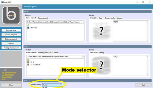
Picture 1: Selection of driving mode
2.1.1 Arcade mode
In arcade mode, a scoring system is active. Your score is presented in the top of the OpenBVE window. Messages in green are displayed in the top of the screen when your score is receiving additional points. Red messages are displayed when points are subtracted from your score.
You get points for correct actions as follows:
- 100 points for stopping at a station where you are expected to stop.
- 15 points if you stop the train within 1 % of the allowed stopping position tolerance.
- 15 points if you stop at the station at the time stated in the time table. You should not be late at all, but also no more than 5 s early.
Points are subtracted from your score for incorrect actions as follows:
- -20 points per minute you are late at a station.
- Up to -50 points if stopping of the stopping mark but still within the allowed tolerance.
- -90 points per minute you leave a station before the time stated in the time table.
- Unspecified points are lost if you open the doors manually outside the station area, loss of points depends on how long the doors are opened.
- Unspecified points are lost if exceeding the permissible speed of the line; loss of points depends on how much you are overspeeding and for how long.
- -100 points if passing a signal at
Stop
. - -20 points for causing discomfort to the passengers. This is likely to happen if breaking too hard, driving too fast through curves or diverting switches etc.
- Unspecified points are lost if your driving forces the train to topple, loss of points depends on the duration of toppling.
- The score is set to -1000 for causing a derailment (if your score is not already at a more negative value
The final score is translated into a percentage between 0% and
100%, which gives a judgement of your driving. In
descending order, the words used are Excellent
, Superb
, Great
, Good
,
Mediocre
, Fair
, Poor
, Bad
, Terrible
and Abysmal
.
2.1.2 Normal mode
In normal mode, there is no score counting. Help messages are shown if you are overspeeding related to the line permissible speed or a speed restricting signal, there are information on time to departure, if you are delayed compared to the time table and so on.
2.1.3 Expert mode
In expert mode, no help messages or markers are shown. You are on your own, so to say.
2.2 Select line and vehicle
During a normal install of OpenBVE a start icon may be placed on the Windows' desktop and one in the start menu tree at the location Start ⇒ openBVE ⇒ openBVE. Use any of these to start OpenBVE.
In the OpenBVE start window you can select which route to drive
and with which train. In the field Start new game
⇒ Route
⇒
Selection
⇒ Browse manually
there are subfolders for one or more routes.
If you have added a lot of routes, there will be a scrollbar to the right of the folder tree. Use it
to scroll down and see all route folders available if necessary. Double-click the directory of the
route you want to drive.
To see the route folders, the path should be set to OpenBVE\LegacyContent\Railway\Route
directory.
If you store your OpenBVE add-ons in your Documents
directory, the full path could be C:\Users\Username\Dcuments\OpenBVE\LegacyContent\Railwat\Route
,
where you replace Username with your username on the computer.
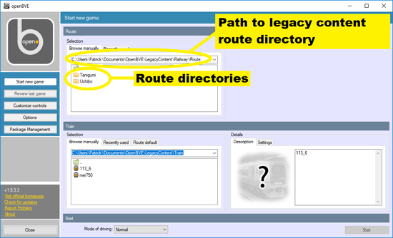
Picture 2: Selection of path and route folder
When the route folder opens, there will be one or more route alternatives to select. They are shown below the folder tree where you selected route folder.
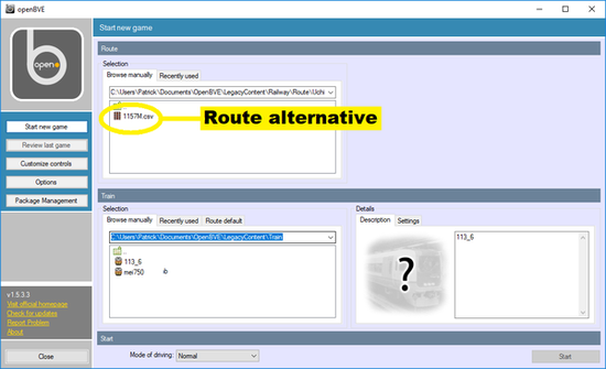
Picture 3: Example of an alternative for the selected route
If there is more than one alternative, the difference may be which type of train is used for the route, such if it is an express route (only stopping at major stations) or a local route or which part of the line the route uses.
By marking (mouse left-click) a route alternative, information on the alternative may be shown in the
field Start new game
⇒ Route
⇒ Details
and information on the default train
to drive in this route Start new game
⇒ Train
⇒ Details
. If, and how
much information that is shown for the route and the train, depends on the authors of the route
and train respectively.
You can, if you wish, select any of the in OpenBVE installed train to drive on a route. This seems convenient, but there may be no sound from the rails and rail joints as these sound comes with the train and not with the route. In the route, however, the sound index for various types of rails is defined. If there is a mismatch between the sound index in the route file and the train file for a specific rail sound, the sounds may be omitted or, at least, not what was intended. As a result of this, the best alternative is usually to use the train that is default train for the route.
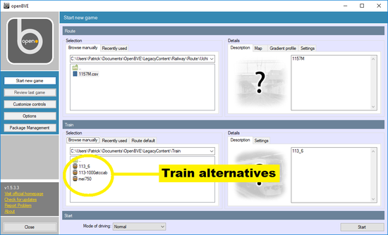
Picture 4: Example of information on train alternatives
Mark (mouse left-click) the train alternative you want to drive with the selected route, or often better,
chose the default train for the route. You select the default train by, in the
OpenBVE start window, going to Start new game
⇒
Train
⇒ Selection
⇒ Route default
and check the box Use the train
suggested by the route
.
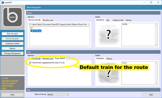
Picture 5: Example of selecting the default train for a route
2.3 The driver's cab
The drivers cab is the traditional view in the BVE and OpenBVE simulation programs. Traditionally, you could not view the train from outside or have other such alternative views. That have changed, and OpenBVE supports outside views of the train. However, most trains available has not support for outside view, so still the driver's view is the main view using OpenBVE.
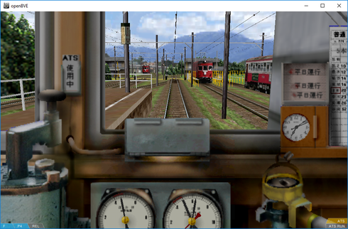
Picture 6: The cab view in OpenBVE of a class 750
Japanese streetcar
The view and the part of the driver's stand visible below the windscreen are intended to look like they do in the real world. However, there are small fields in the screen containing indications from the OpenBVE simulation software. They contain information the help the user, but are not intended to look realistic.
2.3.1 Indicators & controls
2.3.1.1 The driving controls
The driving controls have partially being mentioned before in section 1.4.1. There are two types of controls: One type with separate power and brake handles and another type with the both combined to a master controller. In both cases, there is a separate reverser handle to select forward or reverse driving direction.
2.3.1.1.1 Two controls

Picture 7: Indication of the driving controls' position in case of separate power and brake
handles
To the left, the position of the reverser is indicated
- F = Forward
- N = Neutral
- B = Reverse
The reverser is controlled by using the F and the V key.
In the middle, the position of the power handle is indicated:
- N = Neutral (no power applied)
- P1 = Power step 1
- P2 = Power step 2
- P3 = Power step 3 (and so on)
The number of power steps available depends on the vehicle used; 3 to 5 steps are common. Higher step number means more power applied (speed will increase).
The power handle is controlled by using the keyboard's Z and A keys. Z increases power one notch; A decreases power one notch.
To the right, the position of the braking handle is indicated:
- N = Released (no braking)
- HB = Dynamic/electric braking (not available in all vehicles)
- B1 = Brakes step 1
- B2 = Brakes step 2
- B3 = Brakes step 3
- B4 = Brakes step 4 (and so on)
- EMG = Emergency brakes
The number of brake steps available depends on the vehicle used; 5 to 8 steps are common. Higher step number means more braking (speed will decrease).
The brake handle is controlled by the keyboard's . (period) and , (comma) keys. . (period) increases braking one notch, , (comma) decreases braking one notch.
Emergency brakes are applied using the / (slash) key.
Dynamic or electric brakes cause braking by using the vehicle's electric motors, usually powering the vehicle, as generators. The kinetic energy of the train is converted to electrical energy that is fed back to the overhead wire to be used elsewhere, or is dissipated as heat in electrical resistors by diesel-electric vehicles.
2.3.1.1.2 One control

Picture 8: Indication of the driving control's position in case of a combined master
control handle
To the left, the reverser's position is indicated in the same way as with two control handles. The direction to move is also selected the same way using the F and V keys.
To the right, the position of the master controller is indicated:
- P3 = Power step 3 (and so on)
- P2 = Power step 2
- P1 = Power step 1
- N = Neutral (no brakes nor power applied)
- B1 = Brakes step 1
- B2 = Brakes step 2
- B3 = Brakes step 3
- B4 = Brakes step 4 (and so on)
- EMG = Emergency brakes
As for two handle vehicles, the number of power and brake steps will depend on which vehicle is used. The master controller is controlled by the keyboard's Q and Z keys. The Z key decreases braking one step or increases power one step. The A key increases braking one step or decreases power one step.
If power is decreased with the Q key all way down until the master controller position is
indicated as N
and the Q key is pressed again, braking will start and step up for
each time the Q key is pressed. The Z works the opposite way decreasing braking
down to the N
indication, then stepping up power.
When a master controller is used, emergency brakes are applied by pressing the keyboard's 1 key.
2.3.1.1.3 Old brake systems
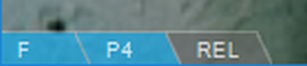
Picture 9: Indication of the driving control's position in case of an old breaking
system and two control handles
The stepped braking action described above doesn't exist in old rail vehicles. Instead of a number of steps, there are only 3 positions for the brakes (plus emergency brakes):
- REL = Decrease braking/release brakes
- LAP = Hold current braking
- SVC = Increase braking
- EMG = Emergency breaks
While driving and the brakes should be fully released, the brake handle should be in the position
REL
. When brakes should be applied, the brake handle is moved to the SVC
position
for a period enough to achieve the wanted braking force. Then the brake handle is quickly moved
to the LAP
position to hold that amount of braking.
To adjust the braking, move the brake handle to SVC
or REL
and the quickly back to
LAP
.
The same keyboard keys, , (comma) and . (period), described in previous section for modern two handle braking systems s are also used with this old braking system. For emergency breaks, the / (slash) key is used.
Using this kind of brakes usually requires a bit of trial and error before a smooth braking can be performed at will. If there is a manometer (see section 2.3.1.4) showing the pressure in the brake pipe, it may help. You then learn about which brake pipe pressure is sufficient for various levels of braking force.
2.3.1.2 The speedometer
The speedometer may be of the traditional gauge type with a pointer or a digital type indicating the speed in numbers. In most vehicles, the speed is indicated as [km/h], with a few exceptions. Note that vehicles assigned to routes where permissible speed is set in [mph] may have speedometers displaying [km/h].
Picture 10: Example of traditional speedometer
![]()
Picture 11: Example of speedometer with digital readout
2.3.1.3 The pilot lamp
The pilot lamp indicates if the train is ready to depart, including that all doors at the train are closed. The train cannot start if the pilot lamp is not lit. The doors are opened automatically by the simulated conductor or the simulated passengers without any action from the train operator necessary.
In OpenBVE it is, however, also possible for the motorman to manually open and close the doors. The F5 key is used to open and close the left side doors, and the F6 key is used to open and close the right side doors.

Picture 12: Example of pilot lamp
Usually a lit pilot lamp indicates that all doors are closed. The opposite exists in a few vehicles. There may also be vehicles with 2 lamps: One lamp indicating doors open and one lamp indicating doors closed.
The state of the left and right side doors are also indicated in the middle of the bottom of the OpenBVE window.
2.3.1.4 The manometers
Pressurized air is used by a train's braking system and other components. There are systems of various operating principles available. Those, however, should not be described here, else than that the operating principle of brake systems used in Japanese trains are usually not the same as used in Swedish trains.
Normally you don't have to pay attention to the manometers (pressure meters) while driving a simulation in OpenBVE.
Pressures in various locations of the system can be indicated. Which pressures that in fact are indicated vary with the vehicle used. These are however the pressures that can be indicated in an OpenBVE simulation:
- Main air reservoir pressure
- Brake cylinder pressure
- Straight air pipe pressure
- Equalizing air reservoir pressure
Usually the pressure is indicated in the unit [kPa], but the unit [kg/cm2] may occasionally be used.
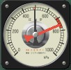
Picture 13: Example of a manometer indicating the main air reservoir pressure (red pointer)
and the equalizing air reservoir pressure (black pointer).
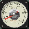
Picture 14: Example of a manometer indicating the straight air pipe pressure (black pointer) and
the brake cylinders pressure (red pointer)
2.3.1.5 Safety systems
2.3.1.5.1 ATS
There are a couple of safety systems simulated in OpenBVE. ATS follow Japanese standards. The status of the ATS safety system is indicated on the ATS display.
ATS-S is a safety system designed to prevent a
vehicle passing a signal at Stop!
. When a vehicle approaches a signal indicating stop/danger, an
audible alarm starts. Should the train operator not
acknowledge the alarm and apply brakes within 5 s
the safety system will apply emergency brakes. Should the train operator in due time acknowledge
the alarm and apply brakes, a reminder signal will sound
which should not be reset until the vehicle has stopped for the red signal.
In OpenBVE, the first alarm is acknowledged by pressing the Space bar at the keyboard. Reset of the reminder signal is done with the keyboard's Insert key.
ATS-P is a safety system designed to prevent a train passing a signal at danger. The system calculates a speed curve of the necessary decrease of the vehicle's speed to be able to stop before a stop signal. Should the train operator at any location of the approach range before the stop signal maintain a speed >10 km/h higher than the system's calculated speed, ATS-P will apply service brakes until correct speed is achieved. Should a vehicle try to start and pass an exit signal in stop position, emergency brakes will be applied.
For those interested in further reading on these systems, there is an excellent article in the magazine Japan Railway & Transport Review no. 21, pages 44 to 50 (Adobe Acrobat document format).
Picture 15: An ATS safety system display
The ATS system can be deactivated using the keyboard's 3 key. To activate the system again, use the keyboard's 2 key. When a simulation is loaded in OpenBVE, the ATS system, if present, is activated by default. Should the ATS system have initiated an application of emergency brakes, the system must be reset by first deactivating it and then activating it again.
2.3.1.5.1.1 ATS
The ATS indicator lamp is lit (orange color) when ATS-S is activated.
2.3.1.5.1.2 ATS RUN
The indicator lamp is lit or flashing (red color) when ATS-S has detected a signal at danger and the driver has not acknowledged the audible alarm and applied brakes.
2.3.1.5.1.3 P POWER
The indicator lamp is lit (green color) when ATS-P is activated.
2.3.1.5.1.4 PTN APPROACH
The indicator lamp is lit when approaching the speed calculated for the breaking curve by the ATS-P system.
2.3.1.5.1.5 BRAKE RELEASE
The indicator lamp is lit (green color) in 60 s when the train operator, using ATS-P, have requested the system to not apply brakes.
In OpenBVE such a request is made by pressing the keyboard's End key. The request is valid those 60 s the indicator lamp is lit.
2.3.1.5.1.6 BRAKE APPLY
The indicator lamp is lit (orange color) when ATS-P has taken action by applying brakes.
2.3.1.5.1.7 ATS-P
The indicator lamp is lit (green color) when ATS-P is activated.
2.3.1.5.1.8 FAILURE
The indicator lamp is lit (red color) if a failure is detected in the vehicle's ATS control unit. It is also lit for a while when the system is activated after being deactivated.
2.3.1.5.1.9 EB
Some vehicles are equipped with a safety device rather similar to what is called a
Dead man's handle
. If the no controls of the vehicle, while it is in motion, are
moved for 1 min, the EB
indicator lamp is lit (green color) and an
audible alert signal sounds. Should that signal
not be acknowledged by the train operator within a few seconds, the train operator is assumed
have falling in sleep or becoming ill and emergency brakes are automatically applied.
In BVE acknowledge of the EB alert is made by pressing the keyboard's Delete key.
2.3.1.5.1.10 CONST SPEED
Some vehicles are equipped with a usable help function that automatically hold the vehicle's speed the same as when the function is activated (similar to a car's cruise control). The CONST SPEED indicator lamp is lit (orange color) when the function is activated.
In Open BVE the function is activated by pressing the keyboard's Backspace key (the key just above the Enter key, usually with a left-arrow on it).
2.3.1.5.2 AWS
AWS is a British safety system designed to prevent
trains passing Stop
signals. A device between the rails sends a signal to the
AWS system in the trains if an upcoming signal shows
Stop!
. An alarm is sounded that needs to be acknowledged by the motorman within
3 s. If the alarm is not acknowledged in time, emergency brakes
are applied to stop the train.
In OpenBVE the Insert key is used to acknowledge the AWS alarm. If breaks are applied by the AWS system, the Delete key is used in OpenBVE the release the brakes.
Not only Stop!
signals but also speed restrictions will use the
AWS. Such AWS
alarms are acknowledged in the same way as described for Stop!
signals above.
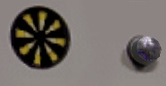
Picture 16: An AWS sunflower
indicator and
acknowledge button
2.3.1.5.3 TPWS
TPWS is another British safety system designed
to prevent trains from passing Stop!
signals. It is always used together with the
AWS safety system.
Train speed is measured by devices on the track before signals showing Stop!
or speed
restrictions. If speed is too high during the upcoming signal aspect, the train will be braked
to stop. Before Stop!
signals there will always be an alarm that should be acknowledged
to avoid automatic braking.
The same keyboard keys are used for TPWS as for AWS, see 2.3.1.5.2 AWS above. The difference is that you cannot reset the TPWS system after an automatic breaking before the trains has being at a standstill for 60 s.
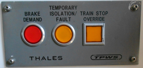
Picture 17: A TPWS control panel
2.3.1.5.3.1 TPWS brake demand indicator
The TPWS brake demand indicator is the red round indicator lamp to the left of the TPWS control panel. It flashes red while a brake demand is issued from the TPWS system. If the TPWS reset button is pressed, the indicator lamp glows solid red.
2.3.1.5.3.2 TPWS Temporary isolation/Fault indicator
The TPWS Temporary isolation/Fault indicator is the center yellow round indicator lamp at the TPWS control panel. The indicator lamp glows solid red if the TPWS is faulty or isolated.
2.3.1.5.3.3 TPWS train stop override button/indicator
The TPWS train stop override button/indicator
is the right square yellow button/indicator lamp at the
TPWS control panel. If pressed, this button
allows the train to pass a Stop!
signal without trigging a
TPWS break demand. The
TPWS override lasts for
20 s after pressing the button. Then
TPWS returns to normal operation mode
automatically.
2.3.1.5.4 ATC (Japan)
The Japanese ATC system is not only intended to prevent
trains passing Stop!
signals, but also to deliver (and enforce) messages on permissible speed.
The permissible speed may be fixed for various parts of the line.
ATC can also set permissible speed dynamically depending
on distance to a train ahead. To use ATC, both
the train and the line must be equipped properly for ATC.
2.3.1.5.4.1 ATC indicator
An active ATC system in the train is indicated by an indicator lamp. How to switch on ATC depends on the train used. See if there are instructions in the OpenBVE.net vehicle catalogue for a specific train class, or see the webpage from where the route and train have been downloaded.
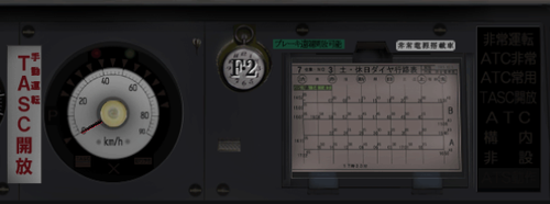
Picture 18: A train control panel with ATC deactivated
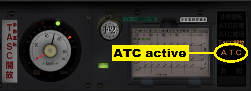
Picture 19: A train control panel with ATC activated
2.3.1.5.4.2 ATC power indicator
On some trains there is an ATC power indicator that is lit when ATC is available on the line, regardless of if ATC is activated on the train or not.
2.3.1.5.4.3 ATC SRV indicator
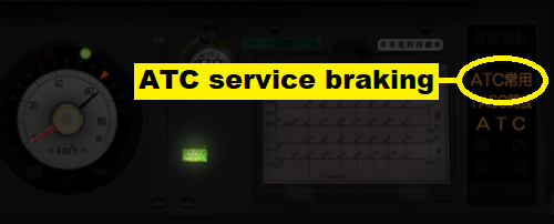
Picture 20: A train control panel with indication on ATC
service braking activated.
2.3.1.5.4.4 ATC EMG indicator
If the train risks passing a Stop!
signal the ATC
system may apply the train's emergency brakes. This may also happen if the line's
ATC signaling stops working and no other safety system
has been activated. For indication, see picture 25 below in
section 2.3.1.5.4.9.
2.3.1.5.4.5 ATC upcoming signal indicator
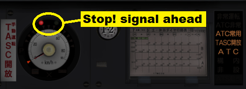
Picture 21: A train control panel where ATC indicates
an upcoming Stop!
signal.
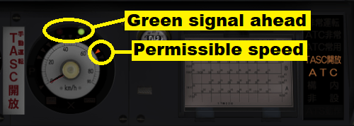
Picture 22: A train control panel where ATC indicates
an upcoming green signal, combined with a permissible speed indication.
2.3.1.5.4.6 ATC permissible speed indicator
Permissible speed is indicated with a red arrow at the speedometer, se picture 22 above.
2.3.1.5.4.7 ATC upcoming speed restriction indicator
Upcoming speed restrictions are announced in advance by a red indicator lamp close to the speedometer. The new speed is not stated, the permissible speed indicator continue to indicate the present permissible speed until the speed restriction takes effect.
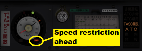
Picture 23: A train control panel where ATC indicates
an upcoming speed restriction.
2.3.1.5.4.8 ATC automatic switching to ATS-P
If the line no longer supports ATC but ATS-P, the train's safety system switches to ATS-P. If there is an upcoming red signal, a breaking curve is calculated and the maximum speed at any given moment is indicated with a red pointer in the speedometer.
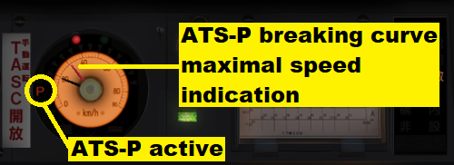
Picture 24: A train control panel where a switch from ATC to ATS-P is indicated
2.3.1.5.4.9 ATC error indicator
If the line's ATC signaling stops working and no other safety system has been activated or is supported, ATC error is indicated. At the same time, the train is emergency braked.
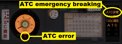
Picture 25: A train control panel where the train's ATC system
indicates that no ATC information is received from the line.
2.3.1.6 Horn & sounds
To sound the horn, press the keyboard's ↵ (Enter) key or the keypad ↵ (Enter) key. Some vehicles may have 2 independent horns. In that case, the other horn is sounded by pressing the keyboard's ⇑ (Shift) + ↵ (Enter) keys, or the keypad's + (Plus) key.
There is a 3rd case, a continuous sound. It is not very common, but the most known example is the traditional bell on American engines. The bell is used as a warning for moving trains in stations, yards and similar places. Also Japanese trains may use continuous sounds, playing a short musical loop as a warning while approaching (over)crowded station platforms.
If it exists, the continuous sound is activated by pressing the keyboard's Ctrl+↵ (Enter) keys. Pressing those keys again deactivates the continuous sound.
2.3.1.7 Miscellaneous controls
2.3.1.7.1 Headlights
On some trains, the headlights can be switched on/off. That is done by pressing the H key.
2.3.1.7.2 Windscreen wipers
On some trains, the windscreen wipers can be controlled by the user. In this case, the Y key increases the speed of the wipers, and Ctrl + Y decreases the speed of the wipers.
2.3.1.7.3 Engine start/stop
On some trains, mainly diesel- or diesel-electric engines or DMU:s, the engine can be started and stopped. The E key starts the engine (you may need to press is for a while if the engine is hard to start), and the Ctrl + E keys stops the engine.
2.3.1.7.4 Pantograph
On some electric engines or EMU:s the pantograph can be moved. The key P raises the pantograph, and the Ctrl + P lowers the pantograph
2.3.1.7.5 Main switch
Some of the electric rail vehicles may have a main breaker that there could be a need to switch. It is done by the B key.
2.3.1.7.6 Live steam injector
The live steam injector feeds water to a steam engine's boiler, replacing the need for a traditional pump for this operation. It uses a steam supply from the boiler for its operation, and can because of that be used both if the train is moving and the train is stationary.
In OpenBVE the live steam injector's operation is toggled on/off by pressing the I key.
2.3.1.7.7 Exhaust steam injector
The exhaust steam injector has a similar function as the live steam injector described above. However, it uses exhaust steam from the engine's cylinders for it operation. This is energy conserving, as no steam from the boiler is used. The exhaust steam would be wasted to the surroundings of the engine if not used to operate the exhaust steam injector.
In OpenBVE the exhaust steam injector's operation is toggled on/off
by pressing the O key (that is the letter O
not the zero key).
2.3.1.7.8 Blowers
The blowers in a steam engine forces air through the smoke stack. The air is taken from the fire and so sucking new air to the fire, boosting heat and steam generation.
In OpenBVE the exhaust steam injector's operation is toggled on/off by pressing the K key.
2.3.1.7.9 Cutoff
The cutoff control in a steam engine controls the steam injection into the engine's cylinders. A high value is used when starting, when you need torque more than speed. To get higher speed with less torque, decrease the cutoff value. This is a simplification; use Google to find more information on steam engine operations.
In OpenBVE the cutoff is increased by the U key, and decreased using the combination Ctrl+U.
2.3.2 AI motorman
In OpenBVE there is a function of a virtual motorman, controlled by AI in the OpenBVE software. This can be used to ride the train as a passenger, and is much convenient if you have trains and routes that graphically suited with exterior view viewing.
In OpenBVE the function is toggled on/off by pressing the key combination Ctrl+A.
2.4 Additional information & help
In the screen there is, depending on the game mode, some information to help you through the simulation. Some additional information depends just on the simulation mode; some are selectable by keyboard commands.
2.4.1 Timetable
The timetable is shown in the upper right part of the screen if Ctrl+T are pressed at the keyboard. To hide the timetable, press those keys once again.
Should the timetable hold to many entries to be fully shown, it can be scrolled. To scroll down, use Ctrl+↓ (Down arrow) at the keyboard. To scroll up, use Ctrl+↑ (Up arrow) at the keyboard.
Picture 26: Example of timetable
For a station/stop entry in the timetable, there are some alternatives for the time entries. That is explained in the table below:
| Time entries | Example |
|---|---|
| Indication | |
| Time of arrival and time of departure | |
| Delay is calculated on the arrival time. The driver will not receive a go signal from the conductor before the departure time (the exit signal may however show a proceed aspect well before the departure time) | |
| Time of departure only | |
| The driver will not receive a go signal from the conductor before the departure time (the exit signal may however show a proceed aspect well before the departure time) No delay will be calculated | |
| Red arrow | |
| No stop should be made at this station (if the signals allow the train to proceed without stop) | |
| Time of arrival only | |
| The final stop, delay is calculated on the arrival time | |
2.4.2 Clock
Pressing the key combination Ctrl+C toggles a clock in the bottom left corner of the screen on/off. The time is shown with 6 digits in the format hh:mm:ss.
2.4.3 The stop position indicator
When stopping in a station, the stop should be made by, or within a certain distance of, the appropriate station stop sign or stop sign. In case of more than one sign, the right sign to stop by should be used. For more on these signs, see section 3 Signs and signals.
As it is hard to accurately get a perception of distance within a few meters in a simulation on a computer screen, a helpful indicator is added in OpenBVE:
![]()
![]()
![]()
Picture 27 a: The white line indicating a stop before the stopping point
Picture 27 b: The white line indicating a stop exactly by the stopping point
Picture 27 c: The white line indicating a stop after the stopping point
A linear scale appears to the right or left in the OpenBVE view. It shows the distance before and after the stopping point stopping is allowed. A white horizontal line shows the train's position. If the white line is above the scale's middle, the train is short of the stopping point. The stopping point is in the exact middle of the scale. If the white line is below the middle of the scale, the train is beyond the stopping point.
How long the distance from the stopping point it is allowed to stop depends on the route. For an ordinary platform the tolerance is usually some ±4--5 meters. If there are doors at the platform that should be in front of the train's doors, the tolerance may be much less.
Should a stop happen to occur before the stopping point and outside the tolerance's limit, correction is made by moving forward towards the stopping point.
Should a stop however occur after the stopping point beyond the tolerance's limit,
correction may be done by moving the reverser handle to Reverse
and move in reverse direction towards the stopping point. Should the stopping point have been
excessively overrun you have missed the station and have to continue forward to next station.
2.4.4 Station information
When you arrive and stop at a station, some information are displayed in the top left corner of the screen. It tells you at which station you have arrived, how much early or late you arrived to the station, and if you underrun or overrun stop marker and with which distance. This information disappears after a few seconds.
Information about the time remaining until departure is expected is also displayed. This information remains on screen until the doors are closed for departure.
2.4.5 Speed
Most rail vehicles have a speedometer in the driver's cab. There is also an alternative in OpenBVE to show the speed in km/h or mph in the screen's bottom left corner.
In OpenBVE this function is toggled km/h / mph / off using the key combination Ctrl + V.
2.4.6 Gradient
In OpenBVE the present line gradient can be shown in the bottom left corner of the screen. The key combination Ctrl + N toggle gradient display modes ‰ / 1:n / off.
2.4.7 Framerate
In OpenBVE the real time framerate can be shown in the bottom left corner of the screen. The key combination Ctrl + X toggles the framerate display on/off.
2.5 Simulation controls
2.5.1 Simulation camera control
The classical view in OpenBVE and in
BVE is the driver's cab view.
In In OpenBVE there is however a number of different
views available. The viewing camera
can be at various positions, and it the camera
can be moved, rotated, tilted and so on as the user wants. For a complete list of the simulation
camera's controls, please see the
Keyboard reference chart
in section 2.6.
Please observe: All trains and routes that works with OpenBVE support the driver's cab view. You can switch to other views in any route, but if the train and route graphics are not built considering other views than the driver's cab view, the result will be disappointing.
2.5.2 Pause
The simulation can be paused and resumed by using the Pause key.
2.5.3 Full screen/Window
The view of OpenBVE can be changed between windowed and full screen mode using the key combination Ctrl + F.
2.5.4 Sound
The sound from OpenBVE can be toggled on/off using the key combination Ctrl + M.
2.5.5 Time acceleration
Time acceleration of the simulation can be toggled 5× (fast) / 1× (normal) using the key combination Ctrl + J.
2.5.6 Quit
To quit OpenBVE immediately, use the key combination Ctrl + Q.
2.5.7 Event markers
As an aid for route developers, there is a function in OpenBVE
that shows event markers
along the track. Those are small signs marking various functions
that are defined in the route, such as signaling, begin and end of stations, sounds to play and so on.
The event markers function is toggled on/off by using the 3-key combination Ctrl + ⇑ (Shift) + E.
2.6 Keyboard reference chart
| Key | Function |
|---|---|
| Case of 1 master controller | |
| Z | Decrease braking/Increase power |
| Q | Increase braking/Decrease power |
| 1 | Emergency brakes |
| Case of 2 driving handles | |
| Z | Increase power |
| A | Decrease power |
| . (period) | Increase brakes |
| , (comma) | Decrease brakes |
| / (slash) | Emergency brakes |
| Gearbox (most found in DMU:s) | |
| G | Shifts one gear up (if train has a gear box) |
| Ctrl+G | Shifts one gear down (if train has a gear box) |
| Reverser | |
| F | From neutral: Forward From Reverse: Neutral |
| V | From neutral: Reverse From Forward: Neutral |
| Sounds | |
| ↲ (Enter) | Horn no. 1 |
| Keypad ↲ (Enter) | Horn no. 1 |
| ⇑ (Shift) + ↲ (Enter) | Horn no. 2 |
| Keypad + (Plus) | Horn no. 2 |
| Ctrl+↲ (Enter) | Toggle continuous sound (bell, melody loop) on/off |
| Keypad - (Minus) | Toggle continuous sound (bell, melody loop) on/off |
| Driver's door control | |
| F5 | Open/close left side doors |
| F6 | Open/close right side doors |
| Electric engines & EMU:s | |
| P | Raise the pantograph |
| Ctrl+P | Lower the pantograph |
| B | Toggle the main breaker on/off |
| Diesel- & diesel-electric engines and DMU:s | |
| E | Start the engine |
| Ctrl+E | Stop the engine |
| Steam engines | |
| I | Toggle live steam injector on/off |
| O | Toggle exhaust steam injector on/off |
| K | Toggle blowers on/off |
| U | Increase the cutoff |
| Ctrl+U | Decrease the cutoff |
| Miscellaneous controls | |
| H | Toggle the headlights on/off |
| Y | Increase speed of windscreen wipers |
| Ctrl+Y | Decrease speed of windscreen wipers |
| ATS | |
| Space bar | Acknowledge ATS-S alarm |
| Insert | Reset ATS-S reminder signal |
| Other control systems | |
| ← (Backspace) | Constant speed control |
| Delete | Acknowledge EB alert signal
(Dead man's handle) |
| Timetable | |
| Ctrl+T | Toggles timetable mode |
| Ctrl+↓ | Scroll down in the timetable |
| Ctrl+↑ | Scroll up in the timetable |
| Simulation | |
| Pause | Pause or resume the simulation |
| Ctrl+A | Toggle AI virtual motorman on/off |
| Ctrl+F | Toggle full screen view on/off |
| Ctrl+M | Toggle simulation sound on/off |
| Ctrl+J | Toggle time acceleration 5× (fast) / 1× (normal). |
| Ctrl+Q | Quit simulation |
| Camera view of simulation | |
| F1 | Train interior view |
| F2 | Train exterior view |
| F3 | Track view |
| F4 | Switch between various flyby views |
| Keypad 1 | Go to previous point of interest along the route |
| Keypad 7 | Go to next point of interest along the route |
| Keypad 9 | Move camera forward |
| Keypad 3 | Move camera backward |
| Keypad 4 | Move camera left |
| Keypad 6 | Move camera right |
| Keypad 8 | Move camera upwards |
| Keypad 2 | Move camera downwards |
| ← (left arrow) | Rotate camera left |
| → (right arrow) | Rotate camera right |
| ↑ (up arrow) | Tilt camera upwards |
| ↓ (down arrow) | Tilt camera downwards |
| Keypad ÷ | Rotate camera counter-clockwise (↺) |
| Keypad × | Rotate camera clockwise (↻) |
| Keypad . (decimal point) | Zoom in |
| Keypad 0 | Zoom out |
| Keypad 5 | Reset camera view to default direction and zoom level |
| Ctrl+R | Toggle interior view camera restriction |
| In-game menu | |
| Esc | Go to in-game menu (while not already in the in-game menu) |
| ↑ (up arrow) | Move cursor up in the in-game menu |
| ↓ (down arrow) | Move cursor down in the in-game menu |
| ↲ (Enter) | Execute selected command in the in-game menu |
| Esc | Go back in the in-game menu |
| Miscellaneous | |
| Ctrl+C | Toggle clock on/off |
| F10 | Toggle various interface modes |
| F11 | Toggle backface culling on/off |
| F12 | Toggle reduced CPU load mode on/off |
| F8 | Toggle route information window: map / gradient profile / off |
| F9 | Toggle route information window: map / gradient profile / off |
| Ctrl+X | Toggle frame rate display on/off |
| Ctrl+V | Toggle speed display km/h / mph / off |
| Ctrl+N | Toggle gradient display modes ‰ / 1:n / off |
| Aid for developers | |
| ⇑ (Shift) + Ctrl + E | Toggle event markers on/off |


 © Patrick Norqvist